Warning: WP_Syntax::substituteToken(): Argument #1 ($match) must be passed by reference, value given in /home/clients/d6e08ef244b0bf1c51b7a99e87ec49b5/sites/mycours.es/wp-content/plugins/wp-syntax/wp-syntax.php on line 383
Warning: WP_Syntax::substituteToken(): Argument #1 ($match) must be passed by reference, value given in /home/clients/d6e08ef244b0bf1c51b7a99e87ec49b5/sites/mycours.es/wp-content/plugins/wp-syntax/wp-syntax.php on line 383
Warning: WP_Syntax::substituteToken(): Argument #1 ($match) must be passed by reference, value given in /home/clients/d6e08ef244b0bf1c51b7a99e87ec49b5/sites/mycours.es/wp-content/plugins/wp-syntax/wp-syntax.php on line 383
Warning: WP_Syntax::substituteToken(): Argument #1 ($match) must be passed by reference, value given in /home/clients/d6e08ef244b0bf1c51b7a99e87ec49b5/sites/mycours.es/wp-content/plugins/wp-syntax/wp-syntax.php on line 383
Warning: WP_Syntax::substituteToken(): Argument #1 ($match) must be passed by reference, value given in /home/clients/d6e08ef244b0bf1c51b7a99e87ec49b5/sites/mycours.es/wp-content/plugins/wp-syntax/wp-syntax.php on line 383
How to work with analog sensors, Arduino and Processing.
Sensors
A sensor is a device that measures a physical quantity and converts it into an electric signal. They can be analog (working like potentiometers) or digital (working like switches). Some examples of analog inputs.
Potentiometer
To introduce the analog input we are going to use a potentiometer. It’s sometimes referred as “pot” by people who don’t smoke weed.
They are usually trimmers (think about the old radio knob) or sliders (think about a audio mixing console).
This is the symbol used in the schematics:
It looks like a resistor because it is a resistor, a variable one. The third pin (W in the scheme) is mechanically movable and correspond to the angle of the trimmer or the position of the slider.
This is the basic way to hook it up:
Potentiometers have 3 leads, the 2 one (usually in the middle) is the one to probe as analog input. The other two should be connected to +5 and mass.
Analog means continuous value as opposed to digital where you have 0 1, LOW HIGH, 0V +5V.
In the Arduino environment it’s an integer value between 0 and 1024.
Note that Arduino has a special set of pin to detect analog inputs marked as A0, A1, A2 etc.
The orientation of the potentiometer will determine the relation between value and know/slider position, try to invert it and see what happens.
In this variable blinking exercise the pot is controlling the delay therefore the blinking speed.
delay(sensorValue);
sensorValue is a value between 0 and 1024 so the blinking will go from 0 delay (LED always on) to 1000ms of delay (1 second on, 1 second off).
Let’s try different potentiometers and sensors now!
Force sensitive resistor

Replace it with the flex sensor, it should work the same way.
(this circuit has a pushbutton as well, that’s a digital input).
Photoresistor

Photocell are basically resistors that change its resistive value (in ohms Ω) depending on how much light is shining onto the squiggly face.
You can use in a laser tripwire.
Reading analog value to control an analog output: an LED in Pulse Width Modulation (PWM) variable brightness.
int LedPin = 11; // LED connected to analog pin 11 int SensorPin = 0; // Pot connected to analog pin A0 void setup() { Serial.begin(9600); } void loop() { int input = analogRead(SensorPin); Serial.println(input); int output = map(input, 0, 1023, 0, 255); analogWrite(LedPin, output); } |
Arduino and Processing
The instructions to make arduino talk to Processing through Firmata are here.
1- Unzip the Processing library and copy the “arduino” folder into the “libraries” sub-folder of your Processing Sketchbook.
(You can find the location of your Sketchbook by opening the Processing Preferences. If you haven’t made a “libraries” sub-folder, create one.)
2- Run Arduino, open the Examples > Firmata > StandardFirmata sketch,
and upload it to the Arduino board.
3- Make this circuit:
4- Run the processing sketch below.
//import the libraries for serial communication //and for arduino/firmata specifically import processing.serial.*; import cc.arduino.*; //this object class Arduino //represents guess what? Your board Arduino arduino; //like in an arduino sketch it's good to //use variables for pin numbers int buttonPin = 13; int sensorPin = 0; void setup() { size(500, 500); smooth(); noStroke(); ellipseMode(CENTER); //the arduino object needs to be created at the beginning arduino = new Arduino(this, Arduino.list()[0], 57600); //once it's created I set the pin modes arduino.pinMode(buttonPin, Arduino.INPUT); arduino.pinMode(sensorPin, Arduino.INPUT); } //we are in processing so the main function is draw (not loop) void draw() { //read a digital value from the button pin int digitalValue = arduino.digitalRead(buttonPin); //change the background accordingly if (digitalValue == Arduino.HIGH) background(255); else background(0); //read an analog value from the sensor pin int analogValue = arduino.analogRead(sensorPin); println(analogValue); //print it for testing purposes //draw a red circle ellipse the size of the analog value fill(255,0,0); ellipse(width/2, height/2, analogValue, analogValue); } |
Try to combine this with knobs (aka potentiometers).
Processing to arduino without Firmata
You can write your own serial communication protocol without using Firmata in case you have very special needs.
Here’s an example with two analog inputs to processing.
Arduino Code:
int sensorValue0; int sensorValue1; void setup() { // initialize the serial communication: Serial.begin(9600); } void loop() { sensorValue0 = analogRead(A0); sensorValue1 = analogRead(A1); Serial.print(sensorValue0); Serial.print(","); Serial.println(sensorValue1); delay(10); } |
Processing code:
import processing.serial.*; int sensor0 = 0; int sensor1 = 0; Serial myPort; void setup() { size(200, 200); // List all the available serial ports println(Serial.list()); // I know that the first port in the serial list on my mac // is always my Arduino, so I open Serial.list()[0]. // Open whatever port is the one you're using. myPort = new Serial(this, Serial.list()[0], 9600); // don't generate a serialEvent() unless you get a newline character: myPort.bufferUntil('\n'); } void draw() { // do your stuff here! } void serialEvent(Serial myPort) { // get the ASCII string: String inString = myPort.readStringUntil('\n'); if (inString != null) { // trim off any whitespace: inString = trim(inString); // split the string on the commas and convert the // resulting substrings into an integer array: int[] sensors = int(split(inString, ",")); // if the array has at least two elements, you know // you got the whole thing. Put the numbers in the // sensor variables: if (sensors.length >=2) { sensor0 = sensors[0]; sensor1 = sensors[1]; } } } |
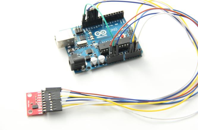
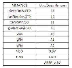
Triple Axis Accelerometer Breakout
Similar to what you have on the wii or iPhone. Senses acceleration in 3 axis, if calibrated detecting the inclination on a plane.
Follow the instructions here
Download the library AcceleroMMA7361 from here
Example code:
#include <AcceleroMMA7361.h> AcceleroMMA7361 accelero; int x; int y; int z; void setup() { Serial.begin(9600); accelero.begin(13, 12, 11, 10, A0, A1, A2); accelero.setARefVoltage(5); //sets the AREF voltage to 3.3V accelero.setSensitivity(LOW); //sets the sensitivity to +/-6G accelero.calibrate(); } void loop() { x = accelero.getXAccel(); y = accelero.getYAccel(); z = accelero.getZAccel(); Serial.print("\nx: "); Serial.print(x); Serial.print(" \ty: "); Serial.print(y); Serial.print(" \tz: "); Serial.print(z); Serial.print("\tG*10^-2"); delay(500); //make it readable } |
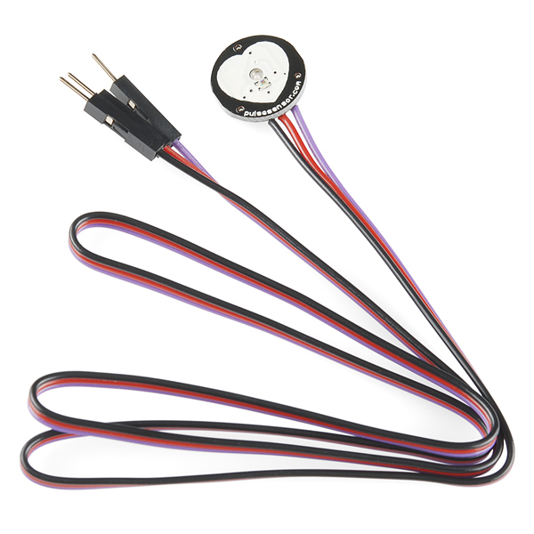
Pulse Sensor
This sensor is well documented.
Refer to the links and example files here


